A5000: Some Success

Having had some time over the weekend to think about options, I realised that rather than spending a very long time, on possibly a hopeless exercise, it might be worth proving that the PCF8583 was really the source of all the problems. I resolved therefore, to try an get the replacement circuit working, in some fashion, and my best ( but ‘dirtiest’ ) option might be to leave the partly installed board in place, with the already connected datalines, and power the circuit off any available 5v line I could find. It wouldn’t be pretty or permanent, but it would demonstrate that any further time spent finding a tidy way of installing this, would ( or wouldn’t ) be a worthwhile investment.

So, I jammed the power wires into the 5V and GND pins of the empty ROM socket and powered on the machine… Holding down the DELETE key I got a flash of a prompt and then dropped into the ‘Desktop’. Success! Smiles all round.

WIMP_success

Just to prove that I wasn’t somehow fooling myself, I unplugged the circuit and low and behold, the Acorn powered on but gave no onscreen prompt or sign of activity  – As before.

It looks like I have found the source of the problem. I just need to find the right way to package the circuit and possible invest in a better soldering iron 🙂


A5000:The Saga continues…

So I set to work with the ‘to-do’ list from the visual inspection of the board. The easiest item on the list was to try and re-solder the battery, which got done fairly painlessly.

Trying to replace the capacitor, wasn’t as successful. As soon as I tried to try anything with it, it pretty much fell off the board and took the solder pads with it. A quick check of the schematic revealed it to be a decouple capacitor, between the + and GND rails, so I (might) be able to live without it, right??

I got a magnifying glass and examined the CMOS/RTC IC (IC58) and the solder joints and legs were looking quite ruined, very likely from the effects of the battery leak. I decided at that point to ‘bite the bullet’ and replace the whole circuit, once again following RetroKits advice and rebuild the CMOS/RTC circuit on an external stripboard.  I managed to by a through hole version of the PCF8583 IC on ebay, which surprisingly arrived within 48hours and I set to work building the circuit.

At this point I was reminded that my soldering skills have either got worse with lack of practice, or they were never up to much in the first place… After a LOT of cursing and looking at some really horrible solder joints, I had the circuit complete.

So, this is the position I now find myself. I’ve tried to make a tidy job of attaching the circuit to the A5000’s mainboard, but so far its not been very co-operative. I’m not helping myself by having to choose between either a small, but underpowered soldering iron, OR one that produces more heat but is also correspondingly ‘fat’.

Before continuing I need to find a more reliable and tidy way of attaching this circuit to the mainboard without causing more damage than I’m fixing. I’m considering trying to push a pin through the appropriate holes on the board, to give me something more substantial to solder to, rather than trying to get wires to solder to essentially ‘test points’. Hopefully I can have another crack at it over the weekend.

A5000: Visual inspection.

I stripped down the Acorn, so that I could remove the mainboard and then very carefully cleaned, with Isopropyl Alcohol, the area where the Battery had previously leaked. I might have been a little too careful, as the photos make the area look filthy, even after a good wash…

Checking over the board, with the help of a magnifying glass, has revealed a couple of obvious problems.

Firstly, Capacitor C169 looks like it’s cracked, so I’ll need to investigate replacing that component.

Secondly, there are areas of corrosion on components and IC’s. I sat with a multi-meter and started checking the corroded looking pins on the ARM processor, mostly Pins 80 down to 70, and all appear to have continuity to the tracks on the mainboard. As the socket is empty, I’m not currently too concerned that this is the source of the boot problems, but it’s worth checking whilst I’m at it. There are some other components, such as surface mount Resistors and Capacitors, that look worryingly corroded on the connections.


From the Retro-Kit page, on restoring A5000’s, similar problems to mine seem to be caused by the RTC/RAM circuit centred around IC58. I found the schematic for the mainboard and checked the connections going to IC58 for continuity the (easy) components such as Resistors. The continuity and resistance checks revealed all was generally OK in the circuit, except for the following:

  • The ground side connection on the Battery appears to be bad; probably a dry joint from my previous poor soldering job.
  • The Positive power ( pin 8 ) to IC58 doesn’t appear very reliable. This is an area that appears to have picked up the worst of the corrosion, so I’m not completely surprised.

So, from what I’ve seen so far, my ‘to do’ list is:

  1. Replace Capacitor C169.
  2. Remove the Rechargeable Battery and resolder, but not before:
  3. Checking the corrosion to Pin 8 on IC58. Possibly cleaning and/or attempting to bridge any break with some solder or jumpwire.
  4. Check for any further damaged components and replace.


If I’m really lucky, this may resolve all the problems. I’m not sure I’m that lucky though.

However, I’m currently working on the principle that I should fix all the obvious, visible, problems first and then dig deeper if required.

A5000 : Initial Assessment

It’s obvious that the Acorn is in bad shape. Last time I booted it up, I got a prompt, now I’m getting nothing.

I’ve done some initial tests and confirmed that I’m getting power from the PSU, to the mainboard, of the voltages I would expect. I’ve also checked the Voltage across the battery and confirmed that is normal.

At this stage and having done some reading, a few possibilities look like good starting points. All of the possibilities relate to the legacy or damage caused by the battery having leaked.

Firstly, the Acorn could be booting and I can’t see the display as has defaulted to a screen setting (resolution and/or refresh rate) that my modern(ish) TFT monitor is very unhappy displaying. I’ve tried holding down ‘DELETE’ on boot-up and also the ‘R’ Key ( which should factory reset the settings), without much success.  Ideally, what I need to do is investigate what the A5000 defaults to for display settings (especially after a reset), and try a couple of different monitors, maybe an older CRT monitor if I can track one down. Also, a possibility might be to build a SCART cable and try it on the CRT TV I do have.

Second, the Acorn could be booting and running, but be faulty in a way that the display does not show anything. Theoretically it should flash the Floppy Drive access LED as a kind of ‘BIOS POST code’, however my Acorn does not have the original Floppy Drive. Quite early on, it became obvious the original drive was faulty, so I simply swapped it for a PC drive, which until now worked fine. It is possible the replacement drive is not showing as the first drive (PC FDD are wired differently with regards to the drive select) and consequently the A5000 is not able to flash the LED. It might not be a bad idea to investigate the drive select and see if I can get the existing drive to produce a status code.

Thirdly, all of the above could be rubbish and wishful thinking. In the end, the old battery has leaked on the mainboard and its highly likely that it has damaged part of the board, which is the root cause of all of the boot issues. I will very likely have to remove the mainboard and visually inspect for damage and clean any residue. Once I’ve inspected the board, I’ll need to repair any obvious signs of damage.

Fortunately, there is a very helpful guide on Retro-Kit (http://www.retro-kit.co.uk/page.cfm/content/Restoring-an-A5000/) which explains some of the diagnosis and repair after just this problem, so I will pretty much follow that and see where I get.

I’d better get my finger out. The halfway point of the month rapidly approaches.

Challenge accepted

Well, it looks like I’m registered on the latest Retro Challenge,so I’d better make a start:

http://www.retrochallenge.org/p/entrants-list-201704.html

What I’ve decided is that I’d like to make an attempt at resurrecting my Acorn A5000.

The machine did originally work, but the all-to-common problem of a rechargeable battery leak happened a couple of years back. I removed the battery and cleaned up most of the resulting mess and the machine appeared to have survived,however it then started to show further symptoms of circuit damage. When powered on, the A5000 refused to boot into the GUI, but instead dropped into a supervisor prompt and all attempts to get any further failed. The Acorn was then packed away for another year or so, with a house move somewhere in the middle, and now fails to boot at all.

My challenge entry will attempt to bring this machine back to life…

Hello? Is this thing on?

Its been a while. I don’t think I had realised just how long its been since I last touched the Blog… I guess its just like a million Blogs, on a million Worlds, which start with good intentions and very quickly wither and die.

For one reason or another, I’ve not really touched my retro collection in at least a year either, so with this years Retro Challenge about to start it seemed like a good motivation to dust off some long packed away hardware and reacquaint myself with some old friends.

Now, all I need to do now is decide what I’m doing as my entry….

http://www.retrochallenge.org/p/blog-page.html?spref=tw

Now, and in colour…

I’ve neglected the Blog and RetroComputing since the end of the RetroChallenge, so here is a note of something really simple, to reheat things.

During July, I dug out my BBC Master to participate in a games event at work. It turned out really well and was a good opportunity to remind myself how the SD Card adaptor, that I fitted a while back, worked. The only downside was the Beeb ended up being plugged into a projector with composite video input, which obviously has become the standard input on displays, and the Beeb has greyscale composite video output, which is a bit disappointing.

Afterwards I resolved to try and fix the ‘problem’ and came across this mod on Sprow’s webpage.

After popping the lid and quickly and carefully soldering the requisite 470pF capacitor in place ( I’m a little embarrassed by the really poor soldering job in the photo, but my excuse is that I was trying to solder quickly to minimise any possible damage ), I tested it. And it works for me 🙂 Tanks in colour!

ColourMod

They think its all over…

Well. Its the end of July ( well, to be pedantic its now August ) and The RetroChallenge comes to an end this weekend, so it seems apt to try and see where I got to with my ‘project’. A personal reflection, if you will.

The good:

A month ago I had been intending to try documenting some of my projects. The badly motivated intention was that even if I’m the only one who looks at this stuff, at least I would have a record of how I solved the problem, or the ideas I had, and I might be able to more easily pick up where I left off. So if nothing else my RetroChallenge entry forced me to start this very Blog – Love it ,hate it, indifferent or self indulgent claptrap…

I’ve dusted off some of my Spectrum collection, found out what works or doesn’t work. I’ve discovered a couple of interesting techniques for loading software and upgraded my +3 to the +3e ROMS – something else I’ve been wanting to do for a while.

The Bad:

My rubber key 48K Speccy is still just as dead as it was a month ago. At some point I’ll have to get my finger out and get it working. But at least I now know.

My +3e still needs a simple IDE interface building, in order to utilise the upgraded ROMS as I intend.

The Future:

Where from here? The past month has forced me to read around the subject a little, (re)discovering ideas and creative peoples projects.The upshot being that I would next like to take a look at fitting a  simple IDE interface to a 48K and utilise Pera’s replacement ROM, possibly on an external cartridge, so I can *hopefully* (fingers crossed assuming I’m reading this right ) recreate the +3e’s ability to load .SNA files, but on a 48K. That was, after all the intention of this project.

More work to do. I’m sure I’ll have stuff to do between now and the next RetroChallenge…

Time for 3e

I first read about the Spectrum +3e replacement ROM’s, from Garry Lancaster, a while back. The ROM’s replace the existing chips, adding a number of features, including the ability to run .Z80 and .SNA snapshots from a Hard Disk drive(SPECTRUM command).

The intention of my RetroChallenge entry was to investigate alternate ways of loading software and in many ways the +3e should represent the perfect embodiment of that desire. Motivated by the ‘RetroChallenge rocket’, I got in touch with Garry and he was very kindly able to supply me with a set of pre-burnt ROM’s. A number of variations on the core enhanced ROM’s are available, depending on the intended hard drive interface to be used. Trying to keep with my original ethic of ‘cheap and simple’, I chose the version of the +3e ROM’s that could utilise the simple 8bit IDE interface, in the hope that I might  be able to DIY build the interface rather than going to the added expense of a bought interface.

Installation was pretty straight forward. I carefully dismantled the +3 and levered out the existing ROMS, putting them to one-side in case I ever want to return the +3 to original, and fitted the replacement. Once reassembled, I was happy that the Spectrum powered up, giving the satisfying +3e boot loader screen (see rather poor quality photo below), without any bangs or flashes…

Success so far, but In order to test the SPECTRUM command, I next need to build the simple IDE interface.

Plus3e_details ROMS

Fun with 3

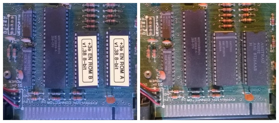
Its time for the +3 to get some attention and it appears to have the widest variety of options for trying alternative ways of loading software.

The first method I wanted to try was attaching a 3.5″ Floppy Drive to the machine, to allow loading of games that have been written to disk on a PC. Some methods of utilising a 3.5″ drive involve replacing the internal 3″ drive, but despite my +3 being a little battered and previously unloved, I do feel lucky to have gotten hold of it ,so I do not have a burning desire to start butchering the case. Fitting an internal drive is therefore out of the question.

When I initially researched the problem, I came across this informative forum post on AmiBay, which details adding a 3.5″ external drive using the B: drive port on the back of the Amstrad CPC, which shares some similarities with the Sinclair +3.  It also describes making a couple of modifications to the drive itself, but researching further it appears that permanent modifications to the drive are not necessarily required. The HD Floppy sensor could be removed/bypassed, however taping over the hole on a HD disk or using DD floppies would negate the need.

I’ve also read some contradictory information about the requirement for a Ready signal. The Amibay post suggests a solder joint on the drive to force pin 33 low , however part of this WIKI post imply’s that a  permanent Ready signal will cause boot problems when a disk is not present. For simplicity and testing, I took a cue from this WIKI ( again a CPC related document ) and decided to make up a small soldered jumper, for fitting between pin 33 and 34, therefore I could add or remove the signal at will.

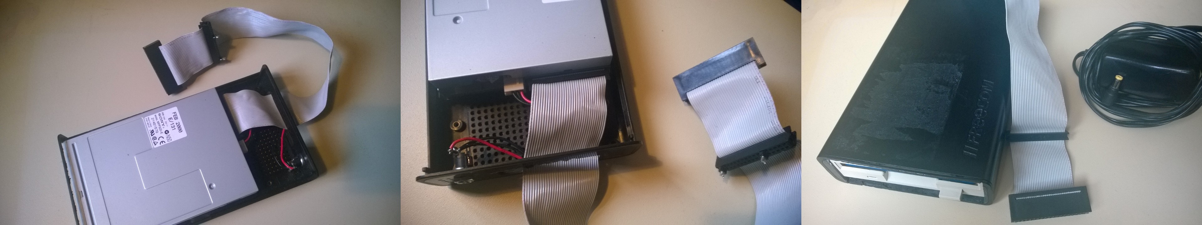
Putting this all together, I used an old 3.5″ external USB HDD caddy that had the guts removed and a suitable opening on the front cut out to access the floppy drive, once fitted. Using an old PC floppy drive cable, I removed the section of cable after the first 5.25″ drive edge connector, as the Spectrum drive wants a straight through cable and the second half, with a twist, was redundant. I also fitted a small power connector to the case, to accept a +5v ‘wall wart’ PSU, connecting internally to the floppy drive power connector, but using only the +5v pins ( The Amibay post implied that most 3.5″ FDD only require 5v). I also then used my small solder jumper to connect pins 33 and 34 together, by pushing the jumper into the spare 3.5″ drive connector on the cable. Also, after a bit of further reading I realised I might be able to get the external drive to override the internal drive for A: drive for priority, by similarly jumpering pins 11 and 12 ( as per the CPC WIKI article.

A picture is worth a thousand words:

ThreeImages

Plugging in didn’t cause my +3 to explode in a shower of sparks, so it passed the first test…

Next I need some disk images. World of Spectrum has some disk images, with an explanation of the Copyright status of the images, from which I downloaded a .dsk file and used Simon Owens SAMDisk utility to write the image to a real 3.5″ floppy disk, using my PC – Unfortunately the utility does not allow the use of USB drives, so a real drive is required.

Inserting the disk in the Spectrum and selecting the “Loader” option, caused disk activity on both drives, but eventually the 3.5″ drive started to seek and fairly quickly loaded the game in question. Success!

At the moment the drive is a little messy. I probably really ought to tidy it all up, possibly replacing the jumpers with toggle switches. It works reasonably well, although it requires a  PC with a internal drive to write the disks and is limited in the games it can play by what was published on floppy disk.It has, however, been constructed from spares and cost me nothing to make.

If anyone does read this a replicate the process, I wish you luck, but you do it at your own risk. I will not be held responsible for any damage to yourself or anything else.